© All Rights Reserved Sandkuhl Clay Works, Inc. 2014-2016

Manufacturer of Ceramic,
Structural Clay and
Refractory Products for
Construction, Agriculture,
Commercial and Industrial
Applications Since 1912.

Rumford Fireplace Installation Instructions
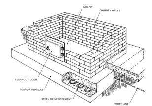
1. Foundation and Preparation
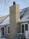
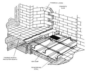
Prepare the supporting foundation for a Rumford using the same construction practices as for a traditional masonry fireplace. Figure 1 shows a cross section for a Rumford and how the components fit into the total fireplace. Table 1 lists the minimum hearth base dimensions required for each size of Rumford. As with all masonry construction, the foundation must be adequately designed to support the weight of the fireplace and chimney. Some typical construction designs are shown in Figure 2. Local building codes should be reviewed for specific requirements concerning foundation construction. For the minimum requirements contained in most building codes please refer to BIA Technical Notes on Brick Construction, Residential Fireplace Design 19.
3. Constructing the Firebox
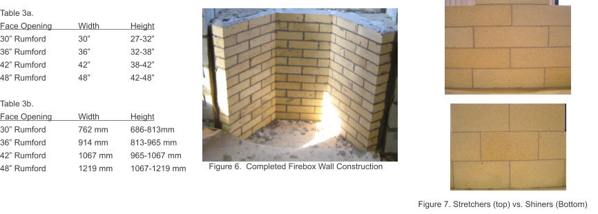
Construct the walls of the firebox according to the dimensions provided in Table 3 that correspond to the size of the fireplace. Use approved refractory mortar maintaining 1/16” to 1/8” (2-3mm) joints. Be sure to use proper back-up behind the firebox with appropriate fill. 75% solid concrete blocks are preferred. Be sure to maintain proper clearances to combustibles throughout construction. See Appendix A for a summary of clearances and other code considerations.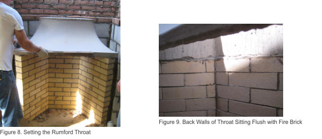
4. Setting the Rumford Throat
After completion of the firebox walls, set and mortar the throat to the firebox with refractory mortar (Fig. 8). Note that the fire box walls should be flush with the interior of the throat (Fig. 9). There should be no ledges in the firebox where the throat the brick meet.
7. Setting the 1st Flue Liner and Building the
Chimney
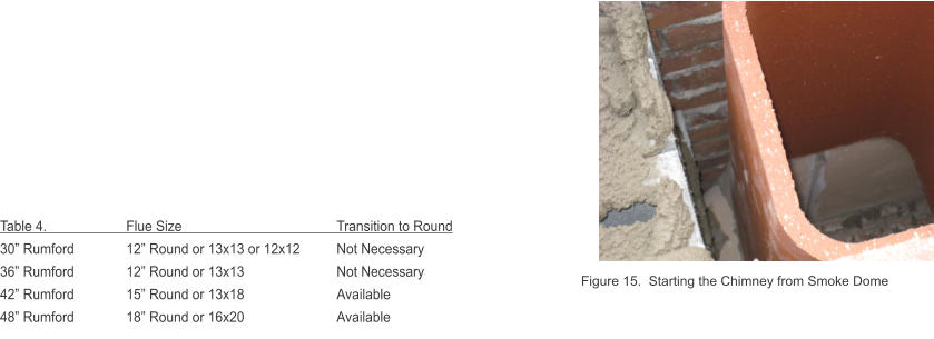
Using refractory mortar, attach the first flue liner to the smoke dome and proceed with normal chimney construction (Fig. 15). If using a round flue liner and transition ring, position and mortar the transition piece onto the smoke dome and proceed with normal chimney construction Recommended flue sizes and transition rings are listed in Table 4. Take care that all interior transitions are smooth and free of mortar and other obstructions to eliminate horizontal surfaces onto which creosote might accumulate during operation. For any questions regarding chimney construction details, please refer to BIA Technical Notes 19b.Appendix A. Clearance to Combustibles (and other important details to avoid mistakes and code violations)
Note: for outdoor patio fireplaces building codes normally do not apply. Check with your local jurisdiction. Framing All combustibles must be a minimum of 2” away from the masonry If the fireplace is on an outside wall, combustibles must be 4” from the masonry. Framing headers must be at a minimum of 3’0” above the top of the fireplace opening as well as 2” away from the masonry. Fireplace Firebrick must be backed up with 75% solid masonry creating walls minimum of 8” thick. The masonry surrounding the smoke chamber must be a minimum of 6” thick measured from the outside to the interior wall. A non-combustible surround must extend a minimum of 6” beyond the interior face of the fireplace. Chimney The size of flue liner is determined by the inside face opening of the fireplace. The flue cross-sectional area required must be a minimum of 10% of the cross- sectional area of the interior face opening. If using round flues, 8% cross-sectional area may be used. There must be a minimum of 2” airspace between the outside of the flue liner and the chimney wall. The chimney wall must be a minimum of 4” thick solid masonry. The chimney must terminate a minimum of 3’0” from the roof and a minimum of 2’0” from any higher point within 10’ of the chimney. Please see Masonry Chimney Construction document for further clarification.
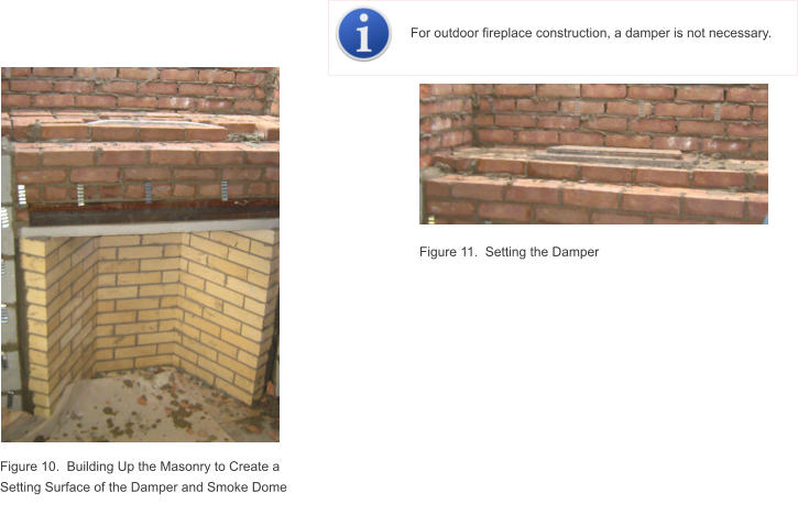
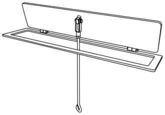
5. Preparing a Base and Installing the Flat Damper
Build up the surrounding masonry to match the elevation of the top of the throat (Fig. 10). Place a steel lentil with the first row of masonry that crosses the front of the throat. This further supports the masonry over the throat (Fig. 10). Build up the masonry, preparing a flat surface onto which the damper and smoke dome can be placed and mortared (Fig.11). When setting the damper (Fig 12), make sure that it will operate properly in conjunction with all surrounding masonry. Check and correct for any interferences in opening, closing or overall operation of the damper.7a. Optional Round Flue Adapter
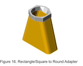
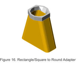
An adapter piece is available for the 42” and 48” Rumford that will convert the square/rectangle opening on the smoke dome to a round opening that is properly sized for the fireplace (Fig. 16). To install, simply mortar the adapter to the smoke dome and proceed with normal construction using round flues.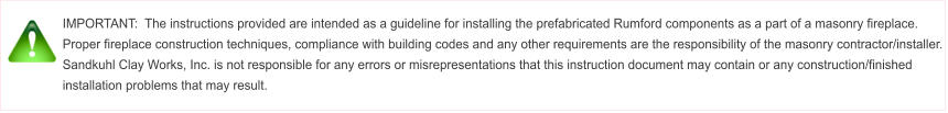


© All Rights Reserved Sandkuhl Clay Works, Inc. 2014-2016

Manufacturer of
Ceramic, Structural
Clay and Refractory
Products Since
1912.
Rumford Fireplace
Installation Instructions
1. Foundation and Preparation
Prepare the supporting foundation for a Rumford using the same construction practices as for a traditional masonry fireplace. Figure 1 shows a cross section for a Rumford and how the components fit into the total fireplace. Table 1 lists the minimum hearth base dimensions required for each size of Rumford. As with all masonry construction, the foundation must be adequately designed to support the weight of the fireplace and chimney. Some typical construction designs are shown in Figure 2. Local building codes should be reviewed for specific requirements concerning foundation construction. For the minimum requirements contained in most building codes please refer to BIA Technical Notes on Brick Construction, Residential Fireplace Design 19.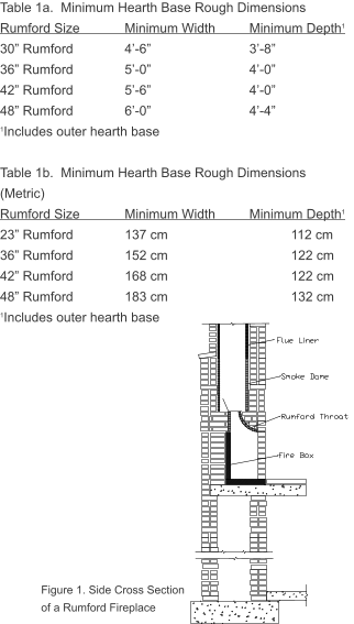
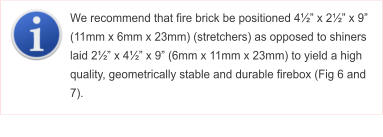
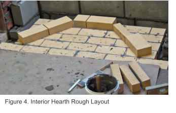

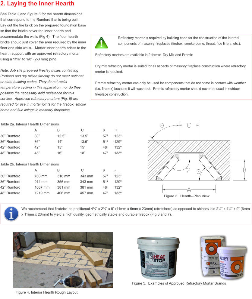
Table 2a. Interior Hearth Dimensions
A
B
C
q
g
30” Rumford
30”
12.5”
13.5”
57°
123°
36” Rumford
36”
14”
13.5”
51º
129º
42” Rumford
42”
15”
15”
48º
132º
48” Rumford
48”
16”
18”
47º
133º
Table 2b. Interior Hearth Dimensions
A
B
C
q
g
30” Rumford
762 mm
318 mm
343 mm
57°
123°
36” Rumford
914 mm
356 mm
343 mm
51º
129º
42” Rumford
1067 mm
381 mm
381 mm
48º
132º
48” Rumford
1219 mm
406 mm
457 mm
47º
133º

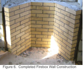
Table 3a.
Face Opening
Width
Height
30” Rumford
30”
27-32”
36” Rumford
36”
32-38”
42” Rumford
42”
38-42”
48” Rumford
48”
42-48”
Table 3b.
Face Opening
Width
Height
30” Rumford
762 mm
686-813mm
36” Rumford
914 mm
813-965 mm
42” Rumford
1067 mm
965-1067 mm
48” Rumford
1219 mm
1067-1219 mm
3. Constructing the Firebox
Construct the walls of the firebox according to the dimensions provided in Table 3 that correspond to the size of the fireplace. Use approved refractory mortar maintaining 1/16” to 1/8” (2-3mm) joints. Be sure to use proper back-up behind the firebox with appropriate fill. 75% solid concrete blocks are preferred. Be sure to maintain proper clearances to combustibles throughout construction. See Appendix A for a summary of clearances and other code considerations.
Figure 8.
Setting the
Rumford Throat
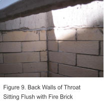
4. Setting the Rumford Throat
After completion of the firebox walls, set and mortar the throat to the firebox with refractory mortar (Fig. 8). Note that the fire box walls should be flush with the interior of the throat (Fig. 9). There should be no ledges in the firebox where the throat the brick meet.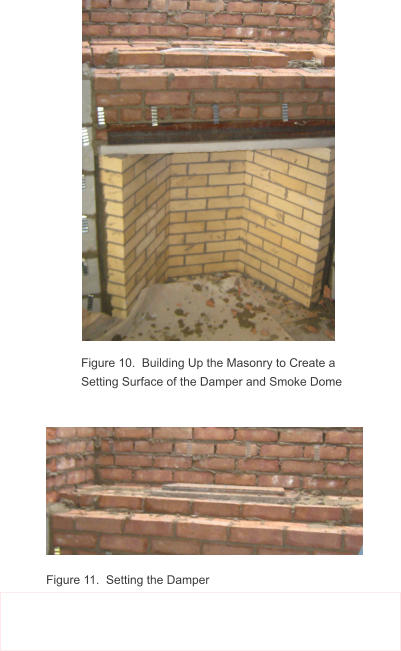
5. Preparing a Base and Installing the
Flat Damper
Build up the surrounding masonry to match the elevation of the top of the throat (Fig. 10). Place a steel lentil with the first row of masonry that crosses the front of the throat. This further supports the masonry over the throat (Fig. 10). Build up the masonry, preparing a flat surface onto which the damper and smoke dome can be placed and mortared (Fig.11). When setting the damper (Fig 12), make sure that it will operate properly in conjunction with all surrounding masonry. Check and correct for any interferences in opening, closing or overall operation of the damper.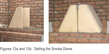
Smoke Dome Dimensions
H
Base OD
Base ID
Top OD
Top ID
30” Rumford
19” 13”x 35”
11”x 32”
13”x 13”
11”x 11”
36” Rumford
19” 13”x 35”
11”x 32”
13”x 13”
11”x 11”
42” Rumford
30” 13”x 35”
11”x 32”
13”x 17½”
11”x 15½”
48” Rumford
30” 15½”x 35”
13½”x 32”
15½”x 19½”
13½”x 17”
Smoke Dome Dimensions (mm)
H
Base OD
Base ID
Top OD
Top ID
30” Rumford
480
330x890
279x813
330x330
279x279
36” Rumford
480 330x890
279x813
330x330
279x279
42” Rumford
762 330x890
279x813
330x445
279x394
48” Rumford
762 394x890
342x813
394x495
342x432
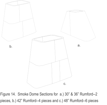
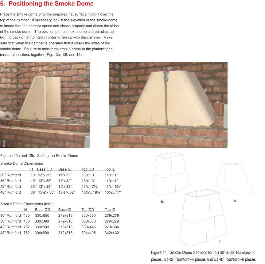
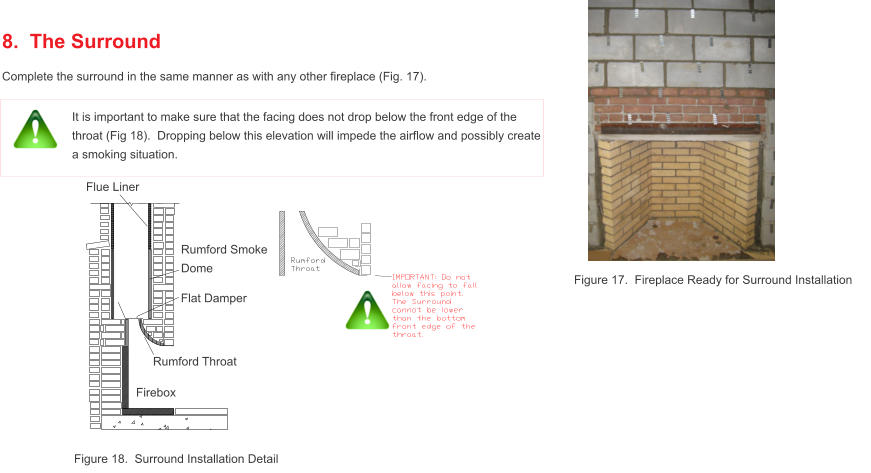
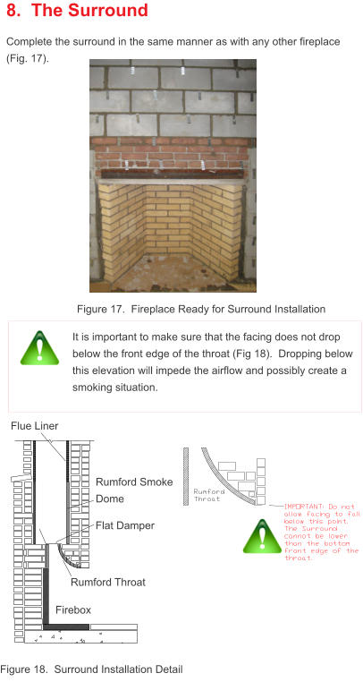
6. Positioning the Smoke Dome
Place the smoke dome onto the prepared flat surface fitting it over the top of the damper. If necessary, adjust the elevation of the smoke dome to insure that the damper opens and closes properly and clears the sides of the smoke dome. The position of the smoke dome can be adjusted front to back or left to right in order to line up with the chimney. Make sure that when the damper is operated that it clears the sides of the smoke dome. Be sure to mortar the smoke dome to the platform and mortar all sections together (Fig. 13a, 13b and 14).
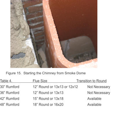
7. Setting the 1st Flue Liner and
Building the Chimney
Using refractory mortar, attach the first flue liner to the smoke dome and proceed with normal chimney construction (Fig. 15). If using a round flue liner and transition ring, position and mortar the transition piece onto the smoke dome and proceed with normal chimney construction Recommended flue sizes and transition rings are listed in Table 4. Take care that all interior transitions are smooth and free of mortar and other obstructions to eliminate horizontal surfaces onto which creosote might accumulate during operation. For any questions regarding chimney construction details, please refer to BIA Technical Notes 19b.Appendix A. Clearance to Combustibles (and other important
details to avoid mistakes and code violations)
Note: for outdoor patio fireplaces building codes normally do not apply. Check with your local jurisdiction. Framing All combustibles must be a minimum of 2” away from the masonry If the fireplace is on an outside wall, combustibles must be 4” from the masonry. Framing headers must be at a minimum of 3’0” above the top of the fireplace opening as well as 2” away from the masonry. Fireplace Firebrick must be backed up with 75% solid masonry creating walls minimum of 8” thick. The masonry surrounding the smoke chamber must be a minimum of 6” thick measured from the outside to the interior wall. A non-combustible surround must extend a minimum of 6” beyond the interior face of the fireplace. Chimney The size of flue liner is determined by the inside face opening of the fireplace. The flue cross-sectional area required must be a minimum of 10% of the cross-sectional area of the interior face opening. If using round flues, 8% cross-sectional area may be used. There must be a minimum of 2” airspace between the outside of the flue liner and the chimney wall. The chimney wall must be a minimum of 4” thick solid masonry. The chimney must terminate a minimum of 3’0” from the roof and a minimum of 2’0” from any higher point within 10’ of the chimney. Please see Masonry Chimney Construction document for further clarification.

7a. Optional Round Flue Adapter
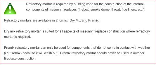
An adapter piece is available for the 42” and 48” Rumford that will convert the square/rectangle opening on the smoke dome to a round opening that is properly sized for the fireplace (Fig. 16). To install, simply mortar the adapter to the smoke dome and proceed with normal construction using round flues.2. Laying the Inner Hearth
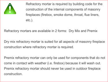
See Table 2 and Figure 3 for the hearth dimensions that correspond to the Rumford that is being built. Lay out the fire brick on the prepared foundation base so that the bricks cover the inner hearth and accommodate the walls (Fig 4). The floor hearth bricks should just cover the area required by the inner floor and side walls. Mortar inner hearth bricks to the hearth support with an approved refractory mortar using a 1/16” to 1/8” (2-3 mm) joint. Note: Job site prepared fireclay mixes containing Portland and dry milled fireclay do not meet national or state building codes. They do not resist temperature cycling in this application, nor do they possess the necessary acid resistance for this service. Approved refractory mortars (Fig. 5) are required for use in mortar joints for the firebox, smoke dome and flue linings in masonry fireplaces.